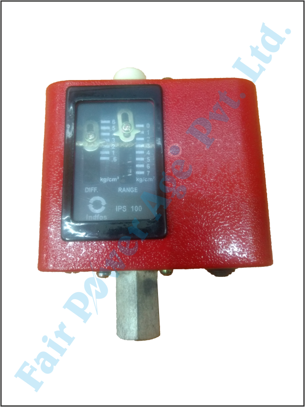
PRODUCT DETAILS
● BELLOWS ACTUATED
● PROVEN RUGGED MECHANISM
● RELIABLE PERFORMANCE
IPS – PRESSURE SWITCHES
Operating Function
Industrial Pressure Switch (IPS) is an electromechanical
device that senses changes in pressure and provides electrical
contact closures at predetermined pressure values.
IPS Pressure Switch may be used to energize an alarm or may
directly control the process by cycling pumps, shifting valves
etc. In an alarm application, the switch protects valuable
equipment by signaling an alarm. In direct control
application, the switch can be linked electrically to other
equipment.
Applications
IPS Pressure Switches are meant for use with oil, water, air,
steam and other non corrosive pressure mediums. They are
not designed for use with any refrigerant gases.
IPS Pressure Switches are used on a wide variety of
applications which include pumps, compressors, turbines,
lubrication systems & condensers to name a few.
Setting
The adjustment knobs are conveniently located on top surface
of the control. The switch can be set to operate at desired
pressure values by adopting following procedure :
1. Decide the maximum pressure at which the switch has to
changeover.
2. Decide the differential at which the control has to operate.
3. First set the maximum changeover pressure on the range
scale. This can be done by removing the knob and turning
the range spindle.
4. Next set the differential on the differential scale with the
help of the differential spindle.
5. Check the maximum and minimum changeover pressures
with a master gauge.
Electrical Connection
On the inside of the front cover, a diagram as shown under is
stamped.
PRESSURE / DIFFERENTIAL
PRESSURE SWITCHES
TYPE IPS / IPSD
GENERAL SPECIFICATION
Enclosure Painted Mild Steel to IP:33 as
per IS:13947 (Part-1), 1993
Sensing Element Phosphor Bronze Bellows
Switching 1 SPDT Contact System
Switch Rating 6A Inductive / 10A Resistive
380V AC, 0.2A Inductive 250V
DC
Repeatability / Accuracy ± 2% FSR
Ambient Temperature 70°C
Process Temperature 100°C max.
Process Connection 1/4" BSP (F)
Cable Entry Suitable for 6 to 14 mm dia
Cable
Mounting Surface / Panel
Type Code No.
Range Differential
Max.
Pressure
atm PSI atm PSI atm PSI
IPS–70 020D8275 0 – 5 0 – 70 0.4 – 4 6 – 55 16 230
IPS–100 020D8276 0 – 7 0 – 100 0.6 – 6 9 – 85 16 230
IPS–200 020D8277 6 – 15 85 – 215 1.4 – 5 20 – 70 32 450
IPS–400 020D8278 6 – 30 85 – 425 3 – 8 45 – 115 32 450
Terminal designations 1, 2 & 3 are engraved on the
transparent cover of the electrical contact system.
The electrical circuit is maintained between contacts 2–1
under normal conditions. The contacts change over to 2–3 on
rise of pressure to preset value.
CHANGEOVER FROM
2–1 TO 2–3 ON RISE
IN PRESSURE
2 1
3
Since the electrical contact is of SPDT type, it can be used for
reverse applications also.
Mounting
The pressure control can be mounted on a wall or panel by
means of mounting holes provided at the back of the device.
Operating Function
Industrial Differential Pressure Switch (IPSD–50) is an
electromechanical device that senses changes in pressure
difference between two pressure lines and provides electrical
contact closures at predetermined values.
Applications
These switches are normally used on pressure lubricated
system across the filter to get an indication or alarm when
the filter gets choked. It can also be used to stop the pump
or energise / de-energise another electric circuit depending
upon the actual application.
It is designed for use with oil, air, water and low temperature
steam. It is not designed for refrigerant gases.
Setting
The lower changeover is set on the scale by rotating the
pressure setting disc inside the control. Clockwise rotation
of the setting disc reduces the set differential pressure and
vice versa. The higher changeover is achieved by adding the
contact differential (2.8 PSI fixed) to the lower changeover.
The setting disc is visible after removing front cover. It is
placed just below the LP bellows between the LP bellows and
main spring.
Fitting
IPSD Differential Pressure Switch can be fitted in any
position. It can be mounted directly or on panel by means of
mounting holes in the back of the device.
The upper bellows is the low pressure element and must be
connected to lower pressure circuit.
The lower bellows is the high pressure element and must be
connected to higher pressure circuit.
Functioning example
IPSD Differential Pressure Switch can be used, to monitor
choking of filters in a lubrication system.
High pressure bellows can be connected to the inlet of the
filter and LP side bellows to the outlet of the filter. The
differential can be set at desired differential pressure which
is adjustable between 4.3 to 64 PSI.
As soon as the pressure difference between the inlet and the
outlet increases above the set difference of pressure by
2.8 PSI, the switch will operate and changeover will take
place to give a signal. It will changeover again when the
difference of pressure falls to the set difference of pressure
to stop the signal.
IPSD – 50 DIFFERENTIAL PRESSURE SWITCHES
GENERAL SPECIFICATION
Enclosure Painted Mild Steel to IP:33 as
per IS:13947 (Part-1), 1993
Range 4.3 to 64 PSI (0.3 to 4.5 atm)
Differential 2.8 PSI (0.2 atm), Fixed
Maximum Pressure 313 PSI (22 atm)
Sensing Element Stainless Steel Bellows
Switching 1 SPDT Microswitch
Switch Rating 5A, 125/250V AC,
0.2A 250V DC
Repeatability / Accuracy ± 2% FSR
Ambient Temperature 70°C
Process Temperature 100°C max.
Process Connection 3/8" BSP (M)
Cable Entry Suitable for 6 to 14 mm dia
Cable
Mounting Surface / Panel
Code No. 060D9002
MOUNTING DIMENSIONS
IPS IPSD–50
All dimensions are in mm
127 75
50 50
105
105
75 190
57
27
This is not a contractual document. Prior notification of changes in specifications is impracticable due to continuous improvement
FOR SWITZER'S OFFICES IN INDIA
CHECK AT:
http://switzerprocess.co.in/index.php?route=information/information&information_id=9
#0715 IPS/IPSD– Rev.1�


